03 HGV access and right of way
When a line on a drawing isn't enough.
A right-of-way change and two new HGV gates, documented as a measured drawing and then built as two interactive models: one to compare existing and proposed, one to test whether an articulated lorry can actually make the turn.
- Project
- Right of way termination and new access gates
- Site
- Waste management site
- Delivered
- Drawing ROW-01 and two interactive models
At a glance
- The problem
- A right of way was changing, and a neighbouring yard needed to know whether articulated lorries could still get in and out.
- What we received
- A proposed site plan, aerial imagery and key measured dimensions.
- What we produced
- A right-of-way drawing for issue, and two interactive models: existing versus proposed, and a gate-width test with moving HGVs.
- What it helped the client do
- A technical access question became something everyone could watch and test, without having to read a swept-path drawing.
01 What we started with
A boundary, a right of way and a neighbour
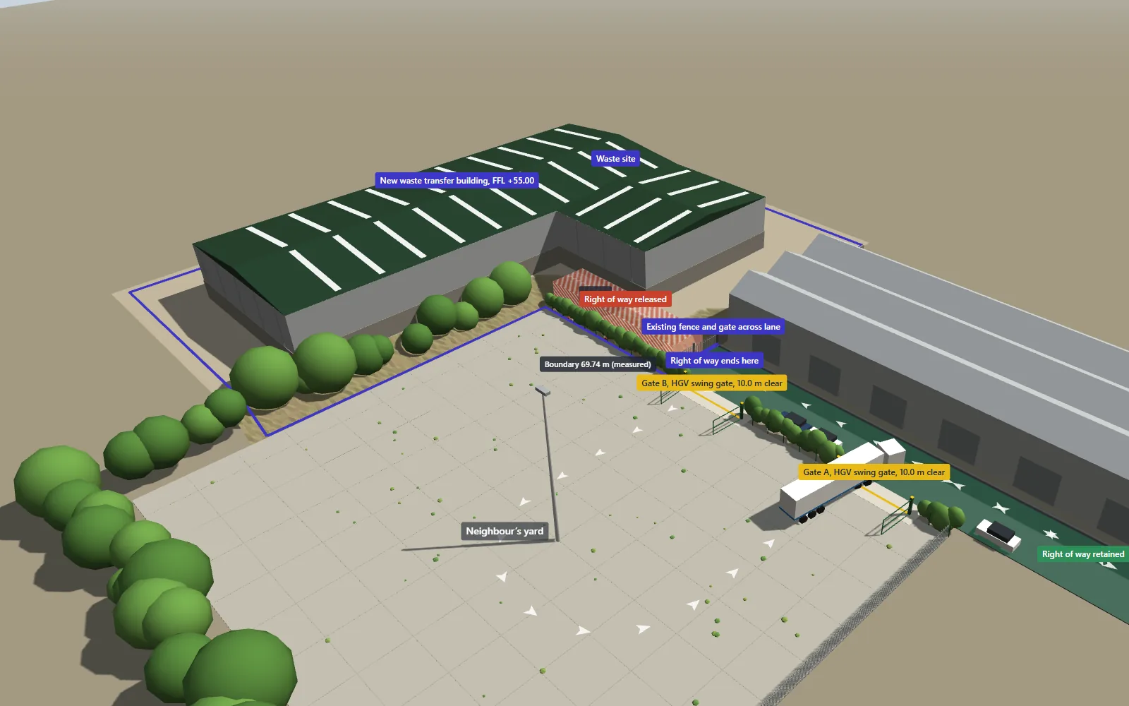
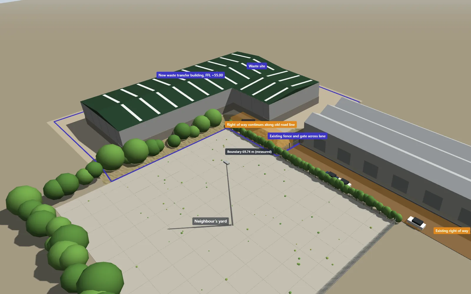
An access lane runs between the waste site and a neighbour's yard. The existing right of way continued past a fence and gate along an old road line that would end up under the batter of a new waste transfer building.
The proposal was to end the right of way at the existing gate and give the neighbour's wagons their own way in and out of the yard directly from the lane.
- The proposed site plan for the new building
- Aerial imagery of the lane, yard and surroundings
- A measured boundary length of 69.74 m and a measured old road length of 23.08 m
- The neighbour's operational need: articulated lorries in and out
02 What we understood
Two questions on top of each other
The first was spatial and legal: where exactly does the right of way stop, and which part is released?
The second was practical: if the neighbour's wagons can no longer use the old road, can a 16.5 m artic get into and out of the yard through new gates in the boundary, and how wide do those gates need to be?
03 What we documented
A drawing that can be issued
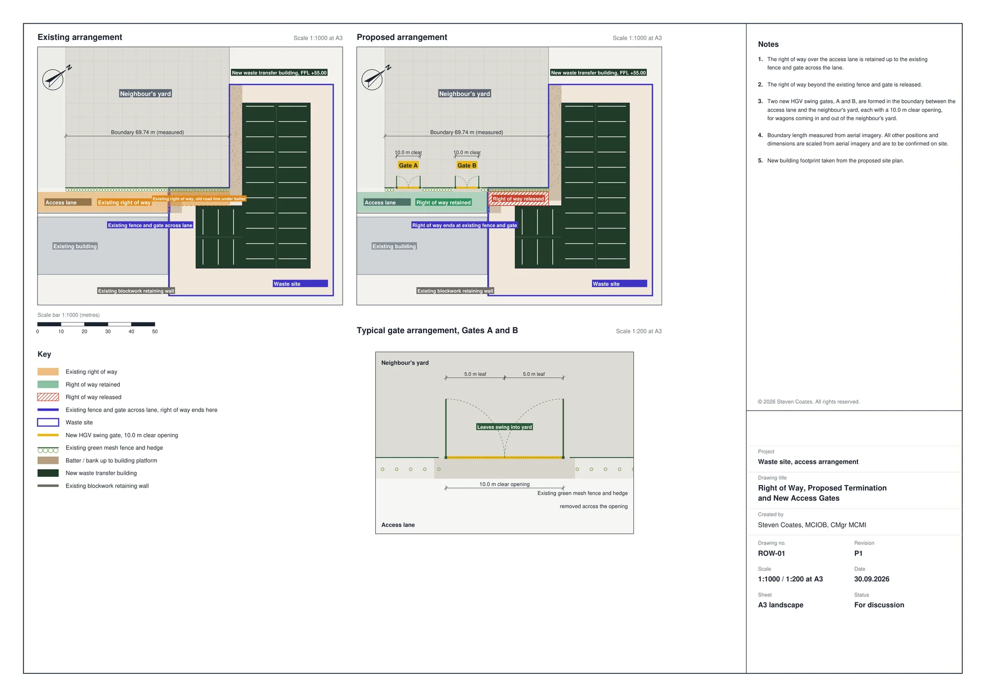
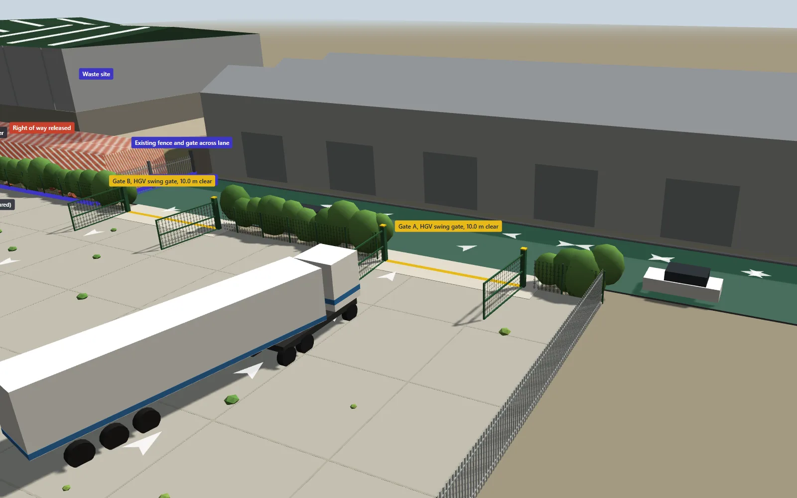
Drawing ROW-01 sets out the existing and proposed arrangements at 1:1000 and a typical gate arrangement at 1:200. It records the measured boundary, the retained and released right of way, and Gates A and B, each a 10.0 m clear opening with two 5.0 m leaves swinging into the yard, with numbered notes on what is measured and what is scaled.
Interactive when you need to understand it. Documented when you need to issue it.
 (opens full size in a new tab)
04 What we built
Two models, one story
The first model compares the existing and proposed right of way in context, with an HGV using the new gates and viewpoints from the lane, each gate, the batter and the new building.
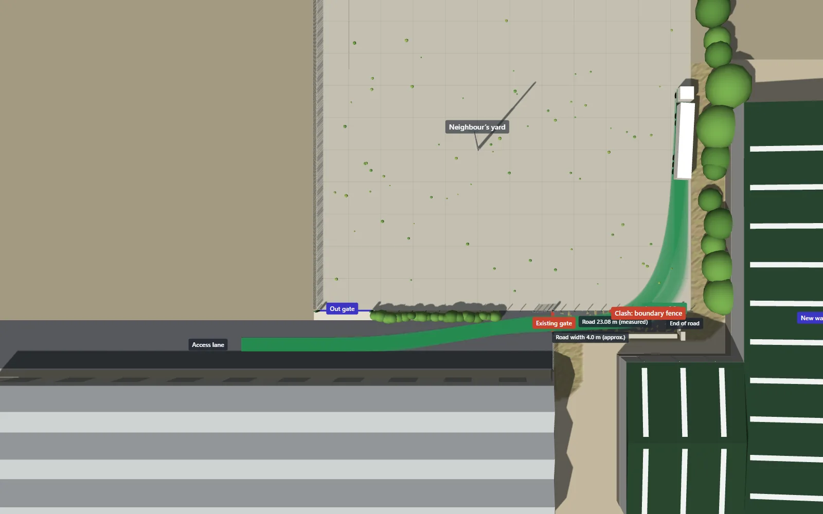
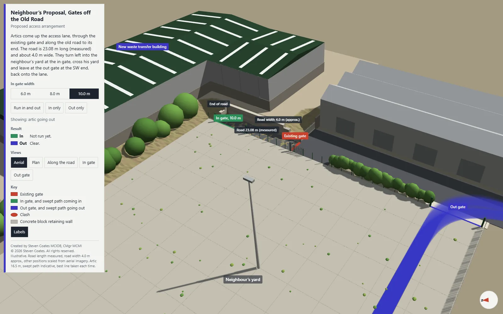
The second takes the neighbour's own proposal, gates off the old road, and lets you test it: pick a gate width, run the artic in and out, and see what it hits.
This is not a render. It is a model you can interrogate.
How to move: Drag to orbit, right-drag to pan, scroll or pinch to zoom.
Model note: Illustrative. Boundary length measured, lane and yard scaled from aerial imagery, new building from the proposed site plan.
How to move: Drag to orbit, right-drag to pan, scroll or pinch to zoom.
Model note: Illustrative. Road length measured, road width 4.0 m approx., other positions scaled from aerial imagery. Artic 16.5 m, swept path indicative, best line taken each time.
05 What you can test
Don't just show the swept path. Show the movement.
A swept-path drawing can prove geometry. An interactive model helps everyone understand what that geometry means on the ground: where the trailer cuts in, which post it meets, and whether a wider gate actually solves the problem.
- Existing versus proposed right of way
- A moving HGV, with gates opening and closing
- In-gate widths of 6.0 m, 8.0 m and 10.0 m
- Inbound, outbound or full runs, with the swept path traced as the vehicle moves
- A result panel that reports Clear, or names each clash
- Aerial, plan, along-the-road and gate viewpoints
06 What it supports
What it helps people decide
Access discussions between neighbours, landowners and operators are easier when everyone is looking at the same moving picture rather than reading lines on a plan.
- Where the right of way should end
- Whether a proposed gate is wide enough, and what it would take to make it work
- Whether a different access arrangement would be better
- How to explain the proposal to people who don't read drawings
Beyond this project
The same approach works wherever space is tight
This project is about waste wagons, but the question is universal: will it fit, will it turn, can it unload, and can it get back out?
- A delivery into a tight urban or construction site
- A HIAB or crane positioning to lift
- A large rigid or articulated wagon turning in a service yard
- Equipment brought through a constrained route to its final position
- A loading bay or dock that has to work alongside other traffic
- Plant entering and leaving a compound
- Alternative access options compared side by side
07 Notes and limitations
Technical notes
- Right of way model: illustrative. Boundary length measured, lane and yard scaled from aerial imagery, new building from the proposed site plan.
- Neighbour's proposal model: illustrative. Road length measured, road width 4.0 m approx., other positions scaled from aerial imagery. Artic 16.5 m, swept path indicative, best line taken each time.
- Drawing ROW-01: boundary length measured from aerial imagery; all other positions and dimensions scaled from aerial imagery and to be confirmed on site.
- The swept paths shown are an illustrative visualisation, not a certified swept-path or transport engineering assessment. Where a formal assessment is required, we visualise the analysis produced by the client's transport consultant.
Start a project
Got something similar?
Send us what you have, even if it's a marked-up drawing or a rough sketch, and tell us what you need people to understand.