02 Waste transfer station layout
Making an industrial layout understandable before it is built.
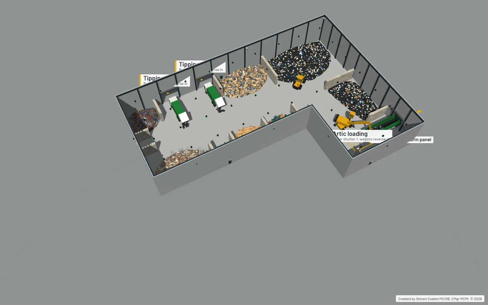
A hand-marked structural drawing for a new waste building, turned into a bay layout drawing and an interactive model of the whole operation: block bays, stockpiles, plant, wagons and building services.
- Project
- New waste transfer building, internal bay layout
- Started from
- A structural grid drawing marked up by hand
- Delivered
- Interactive 3D model and an A3 bay layout drawing
At a glance
- The problem
- A new waste building needed its bays, block walls and plant arranged, and the layout only existed as highlighter on a printed drawing.
- What we received
- A structural grid drawing marked up by hand, plus preliminary services drawings.
- What we produced
- A clean 1:250 bay layout drawing and an interactive model of the whole operation, from stockpiles and plant to lighting and fire detection.
- What it helped the client do
- Operations, design and construction people could work from one clear layout, with vehicles and services shown in context.
01 What we received
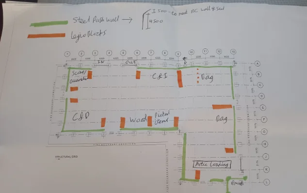
Highlighter on a structural drawing
A printed structural grid drawing for the new building, marked up by hand. Green highlighter showed steel push walls, orange showed where interlocking concrete blocks were wanted, and each bay was written in by waste stream: scrap and quarantine, C&I, C&D, wood, picked items, bagged waste and artic loading.
Preliminary services drawings set out the lighting, fire detection and electrical boards.
 (opens full size in a new tab)
02 What we understood
Reading the mark-up against the grid
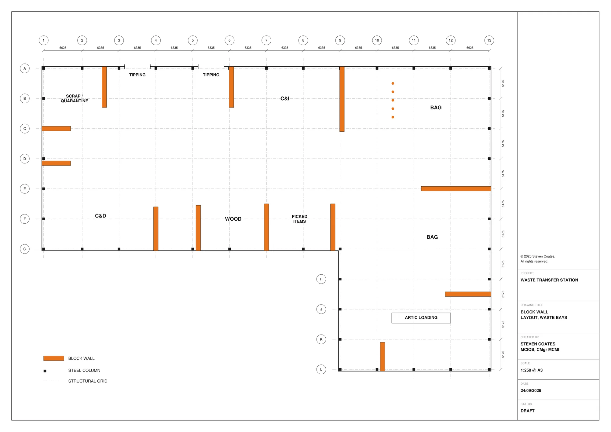
The mark-up was read against the structural grid, at 6,335 mm and 5,175 mm bays, to fix the length and position of every block wall, the tipping doors and the artic loading area.
The question behind it was operational rather than architectural: will the bays, doors, plant and wagons work together as a waste operation, and will everyone involved read the layout the same way?
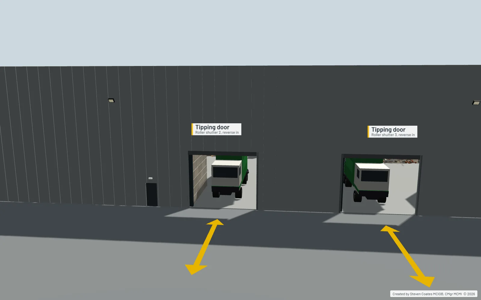
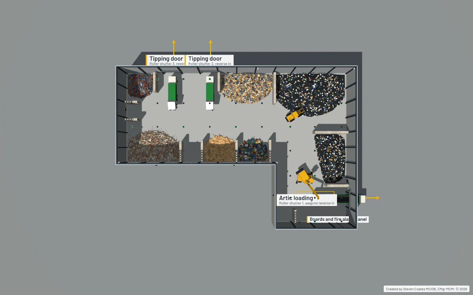
- Two tipping doors on roller shutters, with wagons reversing in
- An artic loading bay through a third roller shutter
- Interlocking block walls at 4.5 m high
- High bay lighting, emergency units, flame detection cameras and call points
03 What we documented
A clean bay layout drawing
The hand mark-up was redrawn as a block wall layout on the structural grid, at 1:250 on A3, so the whole project team works from one clear layout.
 (opens full size in a new tab)
04 What we built
The whole operation in one model
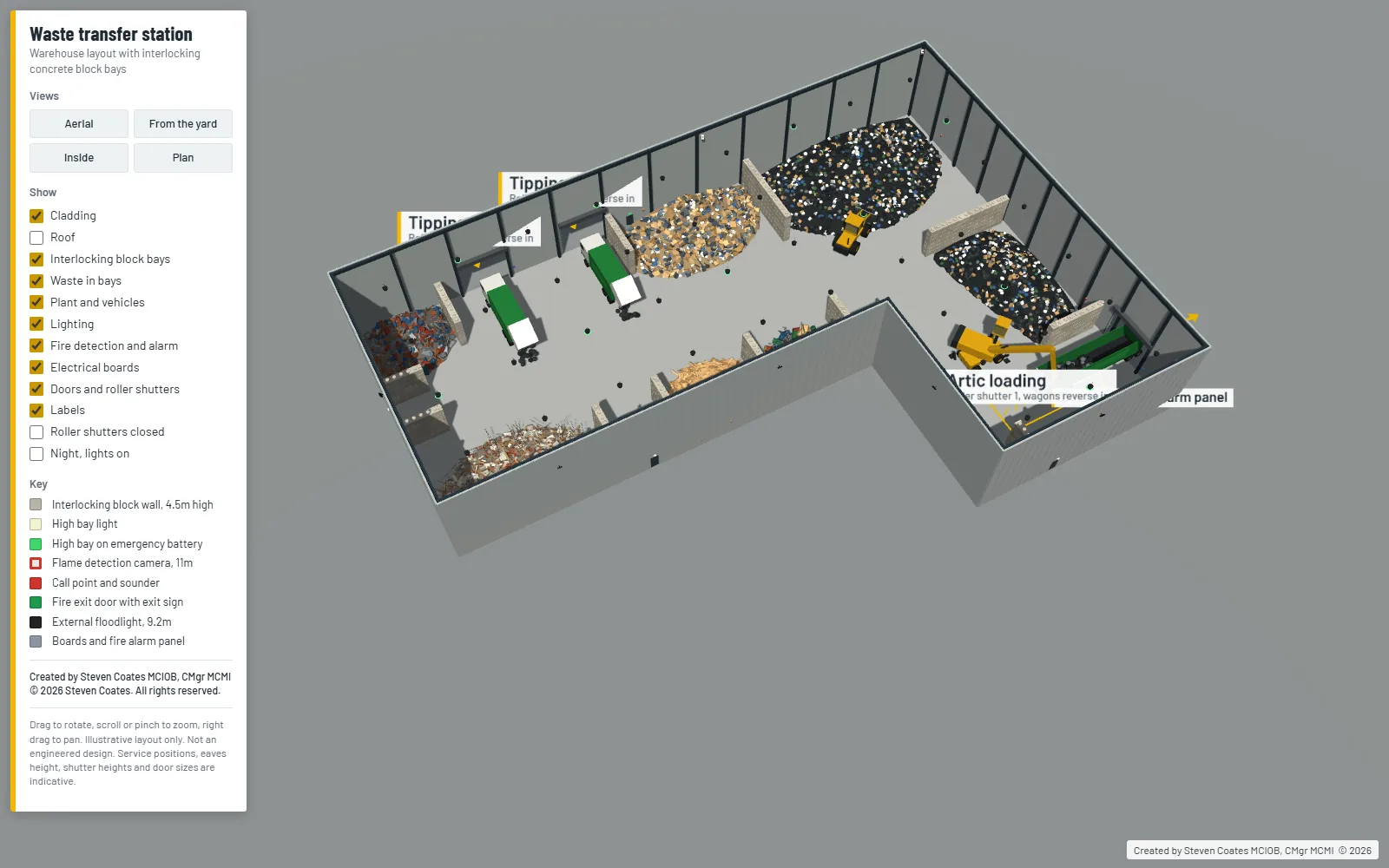
The model shows the building as it would operate: bays filled with representative waste, a loading shovel and grab working the stockpiles, wagons at the tipping doors and the artic at the loading bay, with lighting, fire detection, boards and doors placed from the preliminary services drawings.
How to move: Drag to rotate, scroll or pinch to zoom, right-drag to pan.
Model note: Illustrative layout only. Not an engineered design. Service positions, eaves height, shutter heights and door sizes are indicative.
05 What you can do
Look at it the way each person needs to
An operations manager wants to see bays and vehicles. An electrical contractor wants boards and lighting. A fire-safety adviser wants detection and exits. The same model serves all three by turning layers on and off.
- Aerial, From the yard, Inside and Plan views
- Layers for cladding, roof, block bays, waste, plant and vehicles, lighting, fire detection and alarm, electrical boards, doors and labels
- Roller shutters open or closed
- Night mode with the lights on
06 What it supports
What it helps a team decide
The model gives operations, design and construction people one shared picture to discuss.
- Is each bay the right size and in the right place for its waste stream?
- Can wagons reverse to the tipping doors while the artic is loading?
- Where do lighting, detection and boards sit relative to stockpiles and plant?
- Is everyone agreeing to the same layout?
07 Notes and limitations
Technical notes
- Illustrative layout only. Not an engineered design. Service positions, eaves height, shutter heights and door sizes are indicative.
Start a project
Got something similar?
Send us what you have, even if it's a marked-up drawing or a rough sketch, and tell us what you need people to understand.